Table of Contents
ToggleThe word “micro” means extremely small. It means the microprocessor solve the problem by the small IC. In introduction to microprocessor 8085, evolution, features and bus structure of 8085 are explained.
Evolution of microprocessor 8085
The Intel 8085 is an 8-bit microprocessor introduced by Intel in 1976. It was binary compatible with the more-famous Intel 8080 but required less supporting hardware, thus allowing simpler and less expensive microcomputer systems to be built.
The “5” in the model number came from the fact that the 8085 requires only a +5-Volt (V) power supply rather than the +5 V, −5 V and +12 V supplies the 8080 needed.
S.N. | Year | Name | Word size |
1 | 1971 | Intel 4004 | 4-bit PMOS microprocessor |
2 | 1971 | Intel 4040 | 4-bit PMOS microprocessor |
3 | 1972 | Intel 8008 | 8-bit PMOS microprocessor |
4 | 1973 | Intel 8080 | 8-bit NMOS microprocessor (3-power supplies) |
5 | 1976 | Intel 8085 | 8-bit NMOS microprocessor (Single +5V power supply) |
Features of Microprocessor 8085
The 8085 microprocessor is an 8-bit microprocessor that was introduced by Intel Corporation in the year 1976. It has a wide range of features that make it a popular choice for various applications.
Some of the key features of the 8085 microprocessor are:
- 8-bit Data Bus: The 8085 has an 8-bit data bus that can transfer data between the microprocessor and other devices.
- 16-bit Address Bus: The 8085 has a 16-bit address bus that can access up to 64 KB of memory.
- 3 MHz Clock Speed: The 8085 has a clock speed of 3 MHz, which means it can execute up to 3 million instructions per second.
- 8-bit Arithmetic Logic Unit (ALU): The 8085 has an 8-bit ALU that can perform arithmetic and logical operations on 8-bit data.
- 8-bit Registers: The 8085 has six 8-bit registers (A, B, C, D, E, H, and L) that can be used for storing and manipulating data.
- Interrupts: The 8085 supports five interrupts, which can be used to interrupt the microprocessor’s normal operation. It also has eight software interrupts.
- Serial I/O: The 8085 has two serial I/O ports (SID and SOD) that can be used to communicate with other devices.
- Instruction Set: It provides 74 instructions with only five addressing mode, which includes arithmetic, logical, and control instructions.
- Single +5V Power Supply: The 8085 microprocessor can operate on a single +5V power supply, which makes it easy to use in various applications.
- Low Power Consumption: The 8085 has a low power consumption, which makes it ideal for battery-powered applications.
Overall, the 8085 microprocessor is a versatile and powerful microprocessor that has been used in a wide range of applications, including industrial automation, telecommunications, and consumer electronics.
Bus Structure of Microprocessor 8085
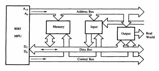
The group of wire which carries binary information from one part of system to another part is known as bus.
Address Bus
- The bus which carries address of a memory is called address bus.
- The address bus is unidirectional: bits flow in one direction-from the MPU to peripheral devices.
- The address bus is a group of 16 lines generally identified as A0 to A15.
- As there are 16 address lines in 8085, total addressing capacity is 216= 64KB.

Data Bus
- The data bus is a group of eight lines used for data flow.
- These lines are bi-directional – data flow in both directions between the MPU and memory and peripheral devices.
- The MPU uses the data bus to perform the second function: transferring binary information.
- The eight data lines enable the MPU to manipulate 8-bit data ranging from 00 to FF (28 = 256 numbers).
- The largest number that can appear on the data bus is 11111111.
Control Bus
- The control bus carries synchronization signals and providing timing signals.
- The Microprocessor Unit (MPU) generates specific control signals for every operation it performs. These signals are used to identify a device type with which the MPU wants to communicate.
Here are some of the important signals of the control bus of the 8085 microprocessor:
- Address latch enable (ALE): This signal is used to latch the address on the address bus during the first clock cycle of an instruction cycle.
- Read (RD) signal: This signal is used to read data from the memory or input/output devices into the microprocessor.
- Write (WR) signal: This signal is used to write data from the microprocessor to the memory or input/output devices.
- Interrupt request (INT) signal: This signal is used to request the microprocessor to service an interrupt.
- Hold (HLDA) signal: This signal is used to temporarily stop the microprocessor from executing instructions and to relinquish control of the system bus.
- Reset (RESET) signal: This signal is used to reset the microprocessor and initialize it to a known state.
Recent posts
Related posts:
- Terminology Used in Microprocessor and Microcontroller
- CISC and RISC Processor Architecture
- Von Neumann and Harvard Architecture
- Basics of Microprocessor and Microcontroller
- Architecture of 8085 Microprocessor
- Pin Diagram of 8085 Microprocessor and Pin Description
- Addressing Modes in 8085 Microprocessor
- Data Transfer Instructions in 8085 Microprocessor
- Arithmetic Instructions in 8085 Microprocessor
- Logical Instructions in 8085 Microprocessor
- Branching instructions in 8085 Microprocessor
- Machine Control Instructions in 8085 Microprocessor
- Timing Diagram of 8085 Instructions
- Stack and Subroutine in 8085 Microprocessor
- Interrupts in 8085 Microprocessor
- Assembler Directives of 8085 Microprocessor
- Simple Data Transfer Program in 8085 Microprocessor
- Microprocessor 8085 Addition and Subtraction Programs
- Programs on Logical Instructions in 8085 Microprocessor
- Multiplication Programs in 8085 Microprocessor
- Division Programs in 8085 Microprocessor
- Introduction to Assembly Language Programming
- 8085 Program to Find the Largest Number in an Array of Data
- 8085 Program to Count Negative Numbers | ALP to Count Negative Numbers
- 8085 Program to Find the Smallest Number in An Array of Data
- 8085 Program to Arrange an Array of Data in Ascending Order
- 8085 Program to Arrange an Array of Data in Descending Order
- 8085 Program to Find the Square of a Number from 0 to 9 Using a Table of Square


