Table of Contents
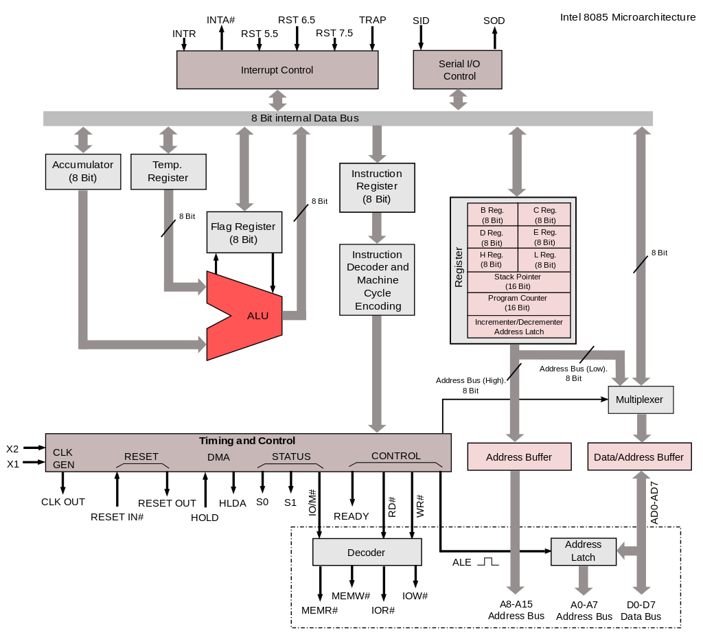
ToggleThe functional block diagram or architecture of 8085 Microprocessor is very important as it gives the complete details about a Microprocessor. Figure shows the Block diagram of a Microprocessor. The block is divided into following types.
- Arithmetic and logical unit
- Timing and control unit
- Interrupt control unit
- Registers
Architecture of 8085 Microprocessor

Arithmetic and Logic Unit (ALU)
- It is used to perform the arithmetic operations like addition, subtraction, multiplication, division, increment and decrement and logical operations like AND, OR and EX-OR.
- It receives the data from accumulator and registers.
- According to the result it set or reset the flags.
- ALU performs these operations on 8-bit data. But these operations cannot be performed unless we have an input (or) data on which the desired operation is to be performed.
- ALU gets its Input from accumulator and temporary register. After processing the necessary operations, the result is stored back in accumulator.
Timing and Control unit
- It has three control signals ALE,
(Active low) and
(Active low) and three status signals
(Active low), S0 and S1.
- ALE is used for provide control signal to synchronize the components of microprocessor and timing for instruction to perform the operation.
and
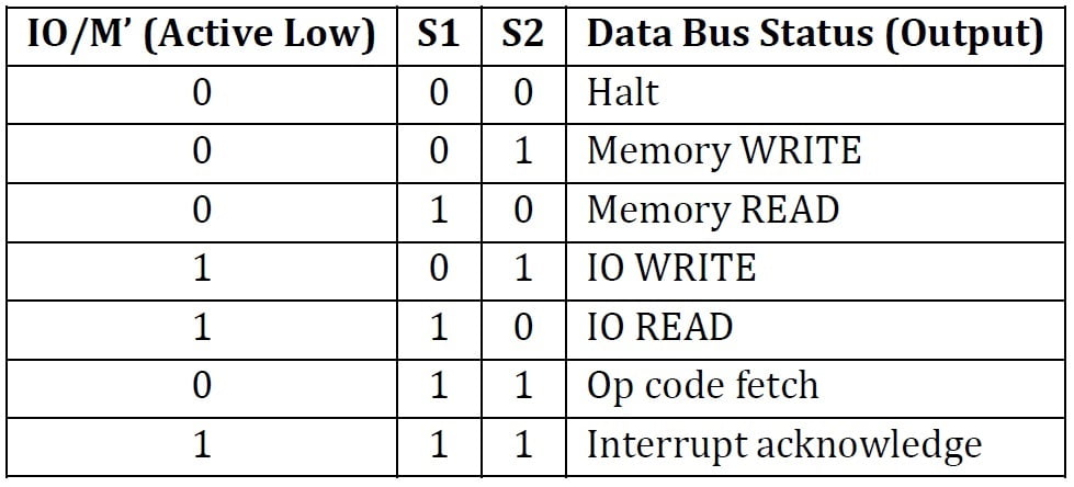
are used to indicate whether the operation is reading the data from memory or writing the data into memory respectively.
If,is used to indicate whether the operation is belongs to the memory or peripherals.

Interrupt Control Unit
- As the name suggests this control interrupts a process. Consider that a microprocessor is executing the main program.
- Now whenever the interrupt signal is enabled or requested the microprocessor shifts the control from main program to process the incoming request and after the completion of request, the control goes back to the main program.
- For example, an Input/output device may send an interrupt signal to notify that the data is ready for input. The microprocessor temporarily stops the execution of main program and transfers control to I/O device. After collecting the input data, the control is transferred back to main program.
- Interrupt signals present in 8085 microprocessor are:
- INTR
- RST 7.5
- RST 6.5
- RST 5.5
- TRAP
Registers in 8085 Microprocessor
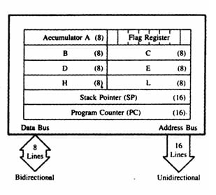
The Intel 8085 microprocessor has a total of 8-bit registers. The registers can be classified into two types: Special Purpose Registers and General Purpose Registers.
General purpose Register
- The 8085 have six general-purpose registers to store 8-bit data during program execution.
- These registers are identified as B, C, D, E, H, and L.
- They can be combined as register pairs-BC, DE, and HL-to perform some 16-bit operations.

Special Purpose Registers
Accumulator (A):
- The accumulator is an 8-bit register that is part of the arithmetic/logic unit (ALU).
- This register is used to store 8-bit data and to perform arithmetic and logical operations.
- The result of an operation is stored in the accumulator.
Temporary Register: It is used to hold the data during the arithmetic and logical operations.
Instruction Register: When an instruction is fetched from the memory, it is loaded in the instruction register.
Instruction Decoder: It gets the instruction from the instruction register and decodes the instruction. It identifies the instruction to be performed.
Serial I/O Control: It has two control signals named SID and SOD for serial data transmission.
Program Counter (PC):
- This 16-bit register sequencing the execution of instructions.
- It is a memory pointer.
- Consider that an instruction is being executed by processor. As soon as the ALU finished executing the instruction, the processor looks for the next instruction to be executed. So, there is a necessity for holding the address of the next instruction to be executed in order to save time. This is taken care by the program counter.
- A program counter stores the address of the next instruction to be executed. In other words, the program counter keeps track of the memory address of the instructions that are being executed by the microprocessor and the memory address of the next instruction that is going to be executed.
- Microprocessor increments the program whenever an instruction is being executed, so that the program counter points to the memory address of the next instruction that is going to be executed.
Stack Pointer (SP):
- The stack pointer is a special purpose 16-bit register used as a memory pointer.
- It points to a memory location in R/W memory (RAM), called the stack.
- Stack pointer maintains the address of the last byte that is entered into stack. Each time when the data is loaded into stack, Stack pointer gets decremented.
- Conversely it is incremented when data is retrieved from stack.
Flag Register (F):
It is an 8-bit register that contains flags that are set based on the result of the arithmetic and logic operations. The program status word of 8085 microprocessor is explained below.
Flag Register / Program Status Word (PSW)
- It includes five flip-flops that are set or reset according to the result of an operation.
- The microprocessor uses the flags for testing the data conditions.
- They are Zero (Z), Carry (CY), Sign (S), Parity (P), and Auxiliary Carry (AC) flags. The most commonly used flags are Sign, Zero, and Carry.
The bit position for the flags in flag register is,

Sign Flag (S):
After execution of any arithmetic and logical operation, if D7 of the result is 1, the sign flag is set. Otherwise, it is reset. D7 is reserved for indicating the sign; the remaining is the magnitude of number. If D7 is 1, the number will be viewed as negative number. If D7 is 0, the number will be viewed as positive number.
Zero Flag (Z):
If the result of arithmetic and logical operation is zero, then zero flag is set otherwise it is reset.
Auxiliary Carry Flag (AC):
If D3 generates any carry when doing any arithmetic and logical operation, this flag is set. Otherwise, it is reset.
Parity Flag (P):
If the result of arithmetic and logical operation contains even number of 1’s then this flag will be set and if it is odd number of 1’s it will be reset.
Carry Flag (CY):
If any arithmetic and logical operation result any carry then carry flag is set otherwise it is reset.
Recent posts
Related posts:
- Terminology Used in Microprocessor and Microcontroller
- CISC and RISC Processor Architecture
- Von Neumann and Harvard Architecture
- Basics of Microprocessor and Microcontroller
- Introduction to Microprocessor 8085
- Pin Diagram of 8085 Microprocessor and Pin Description
- Addressing Modes in 8085 Microprocessor
- Data Transfer Instructions in 8085 Microprocessor
- Arithmetic Instructions in 8085 Microprocessor
- Logical Instructions in 8085 Microprocessor
- Branching instructions in 8085 Microprocessor
- Machine Control Instructions in 8085 Microprocessor
- Timing Diagram of 8085 Instructions
- Stack and Subroutine in 8085 Microprocessor
- Interrupts in 8085 Microprocessor
- Assembler Directives of 8085 Microprocessor
- Simple Data Transfer Program in 8085 Microprocessor
- Microprocessor 8085 Addition and Subtraction Programs
- Programs on Logical Instructions in 8085 Microprocessor
- Multiplication Programs in 8085 Microprocessor
- Division Programs in 8085 Microprocessor
- Introduction to Assembly Language Programming
- 8085 Program to Find the Largest Number in an Array of Data
- 8085 Program to Count Negative Numbers | ALP to Count Negative Numbers
- 8085 Program to Find the Smallest Number in An Array of Data
- 8085 Program to Arrange an Array of Data in Ascending Order
- 8085 Program to Arrange an Array of Data in Descending Order
- 8085 Program to Find the Square of a Number from 0 to 9 Using a Table of Square


