Table of Contents
ToggleAim
Verification of Norton’s theorem
Apparatus
Breadboard, Batteries or DC regulated power supply, Resistors, Digital multimeter, Connecting wires, Alligator clips, Computer and Multisim software for simulation.
Theory
Norton’s theorem is used to convert a complex linear network into a simple network consists of a current source in parallel with a resistor and load resistor.
Statement
- “Any linear circuit containing several energy sources and resistances can be replaced by a single constant current source in parallel with a resistor”.
- it is possible to simplify any complex electrical circuit, to an equivalent circuit with just a single constant current source in parallel with a resistance (or impedance) connected to a load.
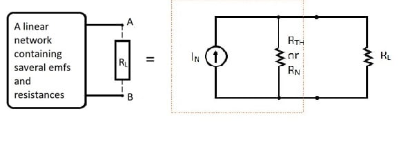
Procedure to convert the given network into Norton’s equivalent circuit
- Find the Norton source current by removing the load resistor RL from the original circuit and calculating the current IN through a short (wire).
- Find the Thevenin’s/ Norton’s resistance (RTH or RN) by removing all power sources from the original circuit (voltage sources shorted and current sources open) and calculating total resistance between open connection points.
- Draw the Norton’s equivalent circuit, with the Norton current source (IN) in parallel with the Norton resistance and load resistance.
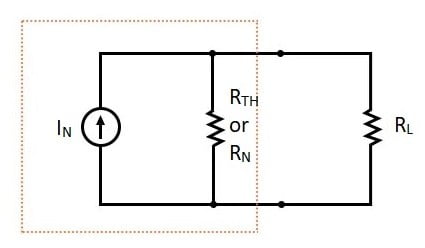
4. Find voltage or current for the load resistor.
Circuit Diagram
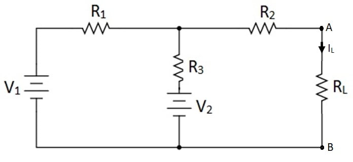
[Preferably chose R1= 2KΩ, R2= 450Ω, R3= 1kΩ and RL=300Ω, V1= 12V and V2= 9V.]
Procedure
- Connect the circuit as shown in the figure 3.
- Measure and note down the current flowing through load resistor RL.
- Remove the load resistor RL from the circuit and short circuit the terminals A and B, shown in figure 4. Measure the current flowing through shorted terminal. This is current IN.
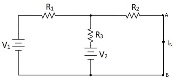
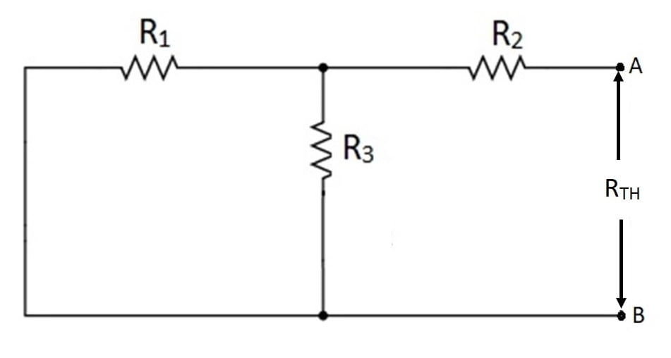
4. Replace the sources with their internal resistances (with removed RL) as shown in figure 5. Measure and note down the equivalent resistance across the terminals from which the resistor RL is removed (between A and B). This is resistor RTH or RN. (Note that Thevenin’s equivalent resistance and Norton’s equivalent resistance is same.)
5. Convert the given network into Norton’s equivalent network and make the connection as shown in the figure 6.
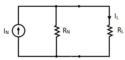
Alternate circuit arrangement for Norton’s equivalent circuit.
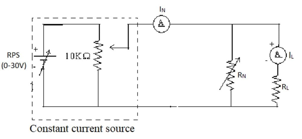
6. Measure and note down the current flowing through resistor RL.
Note: If current source is not available in the laboratory, it can be built by using source transformation. In Norton’s equivalent circuit, the current source IN and a parallel resistance can be converted into voltage source in series with same resistance.
Where, voltage source VS=IN.R
In fact, if we replace above combination i.e. a voltage source and a series resistance then the Norton’s equivalent circuit get converted into Thevenin’s equivalent circuit. Hence Thevenin’s equivalent circuit and Norton’s equivalent circuit is dual of each other.
Precautions
- All the connection should be tight.
- Ammeter must be connected in series while voltmeter must be connected in parallel to the components (resistors).
- Before circuit connection working condition of all the components must be checked.
- The electrical current should not flow the circuit for long time, otherwise its temperature will increase and the result will be affected.
Observation table
Sr. No. |
| RTH | IN | IL |
1. | Theoretical |
|
|
|
2. | Practical |
|
|
|
Calculations
R1=_____ Ω
R2=_____ Ω
R3=_____ Ω
V1 =_____V
V2 =_____V
[calculate IL from figure 3]
[calculate IN from figure 4]
[calculate RTH from figure 5]
The current flowing through load resistor RL in Norton’s equivalent circuit (Fig. 6),
Result
Calculated value of current flowing through load resistor RL in circuit (Fig. 3),
IL= ______A.
Measured value of current flowing through RL in original complex circuit (Fig. 3),
IL= ______A.
Calculated value of current flowing through RL in Norton’s equivalent circuit (Fig. 6 or 7),
IL= ______A.
Measured value of current flowing through RL in Norton’s equivalent circuit (Fig. 6 or 7),
IL= ______A.
Conclusion
As the current flowing through the complex linear circuit and Norton’s equivalent circuit is same/nearly same. It can be determined that any linear network can be converted into Norton’s equivalent network.
That is “Any linear circuit containing several voltages and resistances can be replaced by just one single current source in parallel with a single resistance connected across the load”. Hence Norton’s theorem is verified.
Video Tutorial on Norton's Theorem
Reference Video Tutorial for calculation of Verification of Nortons Theorem
Recent posts
Related posts:
- Verification of Kirchhoffs Laws
- Verification of Superposition Theorem
- Verification of Thevenins theorem
- Verification of Maximum Power Transfer Theorem
- Verify Z-Parameters of Two-port Network
- Verify Y-Parameters of Two-port Network
- Verify Hybrid Parameters of Two-port Network
- Study the transient response of a series RC circuit
- Study the transient response of a series RL circuit


