Table of Contents
ToggleIntegrator is a circuit in which the output voltage is proportional to integration of input voltage. Integrator using Op-amp consist of Op-amp, resistor and capacitor. In this article, integrators are discussed in details.
The integrators are broadly classified into two categories as
- Passive integrator
- Active integrator
Passive Integrator (R-C Integrator)
The passive integrator consists of only passive components. It consists of a resistor and a capacitor connected as shown in the figure.
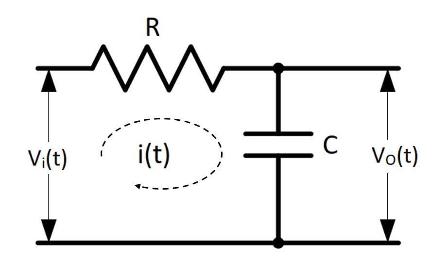
As the resistor and capacitor are passive elements the integrator is called passive integrator.
Let Vi(t) is the instantaneous input signal which can have any shape such as sine, square, pulse, ramp or any other non-standard shape.
VO(t) is the instantaneous output voltage. Let the current flowing through the circuit is i(t).
Expression for Output Voltage
Applying KVL to the passive integrator we get,
where,
VR(t)= instantaneous voltage across resistor =
and VC(t)= instantaneous voltage across capacitor =
…(1)
Multiplying throughout by C, we get
as RC >> T, the term, “” may be neglected
Integrating with respect to t on both sides, we get
Shifting constants from both sides to other one,
…(2)
The output voltage is the instantaneous voltage across R.
…(3)
From equation (2) and (3) we get
…(4)
This is the required expression for the instantaneous output voltage. Thus, he output voltage is equal to the integration of input voltage.
Advantages of Passive RC Integrator
- Simple construction.
- Small size.
- Less cost.
Disadvantages of Passive RC Integrator
- Distortion is introduced in output.
- Output is highly dependent on frequency of input signal.
- Gain is always less than 1.
- Limited frequency range.
Applications of Passive RC Integrator
- As a low pass filter.
- PAM, PWM receiver.
- In active integrator.
Active Integrator using Op-Amp
As integrator circuit has an output proportion to the time integral of the input. An active integrator circuit can be obtained by replacing the feedback resistor of an inverting amplifier by a capacitor.
Ideal Integrator Circuit
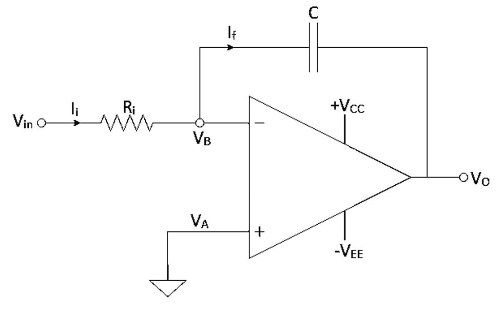
The ideal integrator circuit is as shown in the following figure. It consists of input resistance Ri, a capacitor C is connected from output to input in feedback.
The input voltage Vin is applied at inverting input terminal, the non-inverting terminal is grounded.
Expression for Output Voltage
The input current is Ii and feedback current is If and the output voltage is VO. Let the voltage at non-inverting terminal is VA and voltage at inverting terminal (at node B) is VB.
Applying KCL at node B,
Ii=IF …(5)
Current flowing through the capacitor is given by,
Hence, equation (5) becomes,
…(6)
As node A is grounded B is also at ground by virtual ground concept therefore VB=0. Putting VB=0 in equation (6)
Cross- multiplying above equation,
Taking integration on both sides,
…(7)
The integrator therefore produces an output signal which is proportional to the integral of the input voltage.
Problems / Limitation of an Ideal Integrator
- If input offset error voltage exists, then the voltage also gets added in integrator & gives rise to an error which increases with time.
- Some portion of input bias current also flows through the capacitor & charges it continuously. Hence output voltage increase with time.
- If the integration time is large, then charge into capacitor leaks hence voltage will not be constant for this interval.
- If DC is applied, then capacitive reactance will be ∞, hence gain of integrator will be ∞.
- At high frequency, gain goes on decreasing.
Due to all these problems, ideal integrator is generally not used. The practical integrator is preferred over ideal integrator
Practical Integrator
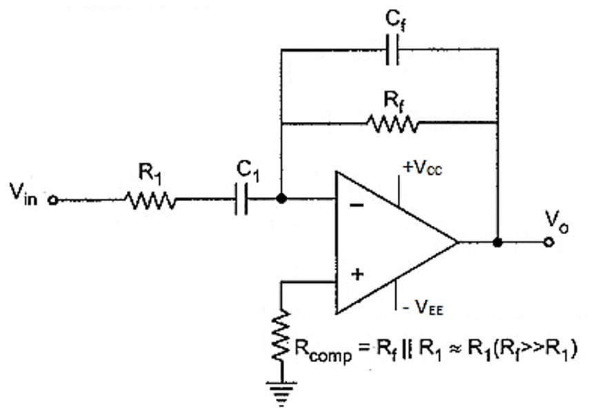
The Rf is added across C because when DC or low frequency is applied gain does not become ∞.
The value of Rf is very high hence it does not affect the circuit operation in any other way.
Rcomp = R1 is used to minimize the error due to offset.
The capacitor can be kept initially charged to any desired voltage by reference voltage source VR.
Advantage of Active Integrator
- Low distortion.
- Controlled gain and highly stable.
- Sharp frequency response.
- Better linearity at output.
- Less effect of noise.
Disadvantages of Active Integrator
- Frequency range is limited.
- Gain reduces with increase in frequency.
- Op-amp parameters affect the output.
Applications of Active Integrator
- The integrator circuit is mostly used in analog computers and wave-shaping circuits.
- As a low pass filter.
- In analog to digital convertors (ADC).
- In the integral type controllers used in closed loop control system.
- In the communication circuits at receiver side for demodulation.
Comparison Between Active Integrator and Passive Integrator
Sr. No. | Active Integrator | Passive Integrator |
1. | Uses Op-amp with resistor and capacitor | Only uses resistor and capacitor, no active device. |
2. | Needs external DC- supply. | Does not need external DC-supply. |
3. | Sharp frequency response. | Frequency response is not sharp. |
4. | Small but slightly expensive. | Small and cheap circuit. |
5. | Less distortion. | More distortion. |
6. | Linear output. | Non-linear output. |

Hi electronicsforyou.in webmaster, Your posts are always well-received by the community.
Hi are using WordPress for yokur blog platform? I’m new to the blog world but I’m trying to get started and set up my own. Do you require any coding expertise to make your own blog?
Anny help would be greatly appreciated!