Table of Contents
ToggleThermal power plants generate electricity by burning coal, a process that inevitably produces flue gases and particulate matter known as fly ash. Fly ash is the fine residue of ash particles carried along with flue gases during combustion.
These particles make up about 85% of the ash content in coal and, if not controlled, can have severe environmental and health consequences.
Impact of Fly Ash Emissions
Uncontrolled fly ash emissions pose significant risks:
- Health Hazards: Inhalation or prolonged exposure to fly ash can cause lung diseases, skin irritation, and other health complications.
- Environmental Issues: Fly ash reduces air visibility, diminishes the intensity and duration of daylight, and precipitates on surfaces, affecting vegetation, infrastructure, and soil quality.
- Aesthetic and Functional Damage: Fly ash deposits can harm agricultural fields and corrode building surfaces.
To mitigate these adverse effects, thermal power plants employ specialized equipment to collect and remove fly ash from flue gases before they are released into the atmosphere through chimneys.
Classification of Fly Ash Collecting Equipment
Fly ash collecting equipment operates by applying a force on the ash particles traversing the gas ducts, directing them towards a collection surface. These systems can be classified into two main categories based on the force used:
- Mechanical Equipment: Utilizes physical means such as gravity or centrifugal force.
- Electrical Equipment: Employs electrical forces, as seen in Electrostatic Precipitators (ESPs).
Methods for Fly Ash Removal
The main methods to separate fly ash from flue gases include:
- Gravity Settling: Uses the natural gravitational pull to remove larger particles.
- Internal Apposition: Relies on internal barriers to capture particles.
- Diffusion and Precipitation: Incorporates natural or induced diffusion processes.
- Electrostatic Precipitation (ESP): Uses electrical charges to collect ash particles efficiently.
Among these methods, Electrostatic Precipitators are the most efficient and widely adopted solution.
Electrostatic Precipitators (ESP)
Overview
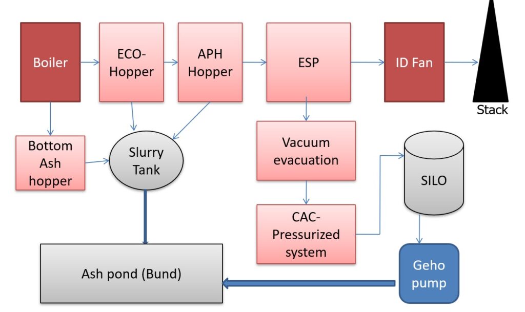
An ESP is a high-efficiency device used to separate fine particulate matter from flue gases by leveraging the electrical properties of the particles. Positioned between the air heaters and induced draft (ID) fans in a power plant, the ESP plays a critical role in ensuring environmental compliance by reducing suspended particulate matter to permissible levels.
Working Principle
The operation of an ESP involves four key steps:
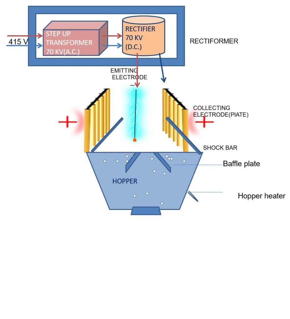
- Ionization of Gas: The gas stream is electrically charged to ionize the particles.
- Particle Migration: Charged particles migrate toward the collection electrodes under the influence of an electric field.
- Particle Collection: Particles are deposited on collection electrodes.
- Dislodging of Particles: A rapping mechanism removes the collected particles into hoppers for disposal.
Detailed Working Mechanism of ESP
Ionization and Charging
The ESP has two main sets of electrodes:
- Emitting Electrodes: Negatively charged wires that create a strong electric field.
- Collecting Electrodes: Grounded plates where charged particles accumulate.
A high-voltage DC current (ranging from 30 to 100 kV) is applied to the emitting electrodes. This creates a corona discharge around the wires, ionizing the gas molecules. The negatively charged ions attach to fly ash particles, charging them and causing them to migrate toward the grounded collecting electrodes.

Particle Collection and Retention
Once the particles reach the collection electrodes, they are held in place by electrostatic forces. The efficiency of this process depends on the resistivity of the fly ash:
- High Resistivity: Leads to stronger particle adhesion, making it harder to dislodge the ash during cleaning.
- Low Resistivity: Causes particles to lose their charge too quickly, increasing the likelihood of re-entrainment into the gas stream.
Optimizing the operating temperature (around 148°C for maximum particle resistivity) and the electrical input ensures effective collection.
Dislodging and Rapping
Over time, collected ash forms a compact layer on the electrodes. To remove this layer:
- Rapping Systems deliver mechanical shocks to dislodge the ash.
- The dislodged ash falls into hoppers at the base of the ESP.
Rapping frequency and intensity are carefully controlled to balance efficiency and avoid re-entrainment of particles.
Construction and Components of ESP

An ESP consists of both mechanical and electrical components:
Mechanical Components
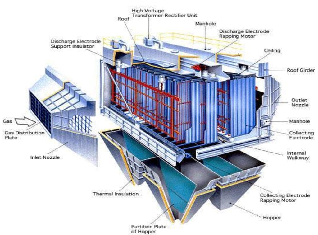
- Casing: Includes wall panels, hoppers, and roof panels. The casing supports all internal components and is designed to allow for thermal expansion.
- Gas Distribution Screens: Perforated plates at the inlet ensure uniform gas distribution across the ESP’s cross-section.
- Emitting Electrodes: Stainless steel wires suspended in a rigid framework create the corona discharge.
- Collecting Electrodes: Roll-formed steel plates that trap the charged particles.
Electrical Components
- High-Voltage System: Includes transformers and rectifiers that generate the required DC voltage for corona formation.
- Auxiliary Controls: Power the rapping mechanisms and heating elements to maintain optimal operating conditions.
Safety and Interlocks
Interlocks ensure operational safety by disabling power supply and grounding the ESP before maintenance activities.
Advantages of ESP
- High Efficiency: Can capture particles as small as 5 microns with an efficiency exceeding 99%.
- Large Gas Volume Handling: Suitable for high-capacity power plants.
- Low Pressure Drop: Minimal resistance to gas flow, ensuring energy efficiency.
- Ease of Maintenance: Collected ash is relatively easy to remove and dispose of.
Operational Considerations
- Gas Velocity: The velocity of flue gases must be lower than the migration velocity of particles to allow sufficient time for collection.
- Particle Size: Smaller particles (<20 microns) are harder to collect, requiring optimized design and operation.
- Temperature and Resistivity: Operating at the right temperature minimizes re-entrainment and maximizes collection efficiency.
Recent posts
Related posts:
- Rankine Cycle in Thermal Power Plants
- Modes of Coal Transportation in Power Plant
- Coal Handling Plant – CHP
- Protections in Coal Handling Plants and Challenges
- Fuel Firing in Boiler
- Boiler Construction: History, Types, and Key Components
- Bowl Mill (Pulverizer) in Thermal Power Plant
- Coal Feeders in Power Plants
- Construction and Working of Air Preheater

