Table of Contents
ToggleDifferentiator is a circuit in which the output voltage is proportional to differentiation of input voltage. Differentiator using Op-amp consist of Op-amp, resistor and capacitor. In this article, differentiators are discussed in details.
Differentiators can be classified into two categories as
- Passive differentiator
- Active differentiator
RC Passive Differentiator
The passive differentiator uses passive circuit elements resistors and capacitors. There is no active element present in the passive differentiator as shown in the following figure.

Expression for Output Voltage
Apply KVL to the input side, we get,
The output voltage is the instantaneous voltage across R.
Solving we get,
…(for RC<<T)
This is the required expression for the output voltage which shows that the output is equal to RC times the derivative of the input.
Input and Output Waveforms of RC Differentiator
Now let us obtain the input output waveforms for different input waveforms. For a pure dc input voltage, the differentiator output will be zero because the capacitor blocks dc.
The waveforms of RC differentiator for a square wave input are shown in Fig.
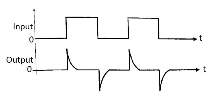
These waveforms are drawn with an assumption that time period of input signal (T) is much larger than the RC time constant i.e. T >> RC.
Note that corresponding to sharp changes in input i.e. for leading and trailing edges, the capacitor acts as a short circuit and allows the output to be equal to input.
Whereas for the flat portion of input (which is equivalent to dc) the capacitor offers an infinite reactance and produces a zero output.
Advantages of Passive Differentiator
- Simple construction.
- Low cost.
- Easy to design.
- Small size.
Disadvantages of Passive Differentiator
- Distortion is introduced in the output.
- Operation is highly dependent on frequency of input signal.
- Gain is less than 1 i.e. signal gets attenuated.
- For proper operation, the time constant has to be small.
Applications of Passive Differentiator
- As a passive high pass filter.
- In the active filter.
- In analog computers.
- In the clock circuit of digital circuitry.
Differentiator using Op-Amp
A differentiator circuit produces differentiated version of the input voltage applied to it. This process is exactly opposite to integration.
Therefore, the components connected in the integrator have interchanged their positions to produce a differentiator circuit of Fig. (R, and C; have interchanged their positions).
In this section we are going to discuss two types of differentiators circuits namely
- Basic or ideal differentiator
- Practical differentiator
Basic Differentiator
The differentiator or differentiating amplifier using op-amp is as shown in following figure.
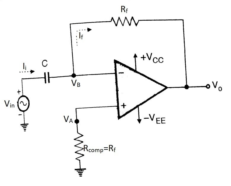
The differentiator be obtained from an inverting amplifier in which the input resistor R 1 is replaced by a capacitor.
This circuit will perform mathematical operation of differentiation on the input voltage waveform and the output is a derivative of the input signal.
Applying KCL at node B,
…(1)
By virtual ground concept,
Putting VB=0 in equation (1)
This is output voltage equation for an active differentiator circuit.
From this equation, it can be concluded that the output voltage of differentiator is -RfC times differentiation of input voltage.
Thus, output of differentiator is depending upon differentiation of input voltage.
Problems / Limitation of an Ideal Differentiator
As frequency increases, Xc reduces i.e. Capacitor draws more current from input source. Thus at high frequency input source gets loaded by capacitor C. Therefore noise signals at higher frequency gets amplified and appeared at output.
The increase in gain due to high frequencies will make the circuit unstable. So to avoid the mis-amplification of the signal the ideal differentiator is modified and referred as practical differentiator or compensated differentiator.
Practical Differentiator
The practical differentiator circuit is as shown in the following figure.
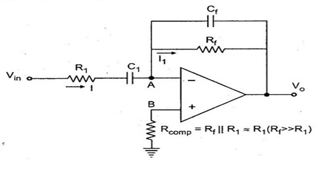
Here two components i.e. R & CF have been added to basic differentiator circuit due to reduction in Xc at high frequencies, the gain of differentiator increase very much.
To stabilize it we have to connect resistor R1 in series with C1. The resistor Rcomp has been used for bias compensation.
At high frequency, the reactance of Cf is small so high frequency noise gets bypassed and not appeared at output.
Advantage of Active Differentiator
- Sharp frequency response.
- Controlled gain.
- Low distortion.
Disadvantages of Active Differentiator
- Op-amp restricted the output frequency.
- Gain increases with frequency.
- It is affected by noise.
Applications of Active Differentiator
- As a high pass filter.
- In wave shaping circuit.
Comparison Between Active and Passive Differentiator
Sr. No. | Active Differentiators | Passive Differentiators |
1. | Uses Op-amp with resistor and capacitor. | Only uses resistor and capacitor. No active device |
2. | Sharp frequency response. | Frequency response is not sharp. |
3. | Requires external power supply. | Does not require external power supply. |
4. | Slightly expensive. | Small and inexpensive circuit. |
For Video tutorial on
“Op-Amp as a differentiator” in Hindi
Recent posts
Related posts:
- Introduction to Op-amp
- Parameters of Op-amp
- Configuration of Op-Amp
- Open Loop Configuration of Op-Amp
- Closed Loop Configuration of Op-Amp
- Virtual Short and Virtual Ground Concept
- Summing Amplifier Using Op-Amp | Adder Using Op-Amp
- Difference Amplifier Using Op-Amp | Subtractor Using Op-Amp
- Integrator Using Op-Amp
- Comparator Using Op-Amp
- Zero Crossing Detector (ZCD)

Dear electronicsforyou.in owner, Your posts are always informative and well-explained.
Dear electronicsforyou.in admin, You always provide valuable information.