Table of Contents
ToggleBoilers are crucial for generating steam in industries ranging from power plants to manufacturing. Defined as closed vessels with capacities exceeding 22.75 liters, they operate under high pressure to convert water into steam. This steam then drives turbines or serves other industrial processes.
Over the centuries, boiler technology has evolved, resulting in more efficient and specialized designs. Here, we’ll dive into the history of boiler construction, types of boilers, their primary components, and the design considerations that ensure safety and efficiency in modern industrial applications.
The Evolution of Boiler Technology
The journey of boiler technology began in the early 18th century. In 1725, the first boiler, known as the “Wagon Boiler,” was developed. This early model operated under a pressure of about 6 to 10 kg/cm² and had a unique design shaped like a wagon.
Over time, the demand for more robust and versatile boilers grew, especially with the expansion of industrialization. By the mid-19th century, engineers developed fire-tube boilers and, subsequently, water-tube boilers, which became widely used in steam-powered machinery and power stations.
Types of Boilers
Boilers can be categorized based on their construction, purpose, and pressure-handling capabilities. The two primary types of boilers are:
Fire-Tube Boilers
- Developed in 1844, fire-tube boilers are among the oldest types and are relatively straightforward in design. The Carnish and Lancashire boilers are classic examples. In a fire-tube boiler, hot gases from fuel combustion pass through tubes surrounded by water.
- The water absorbs the heat, creating steam. Fire-tube boilers are simpler to construct and maintain but generally operate at lower pressures and are suitable for applications with smaller steam demands.
Water-Tube Boilers
Introduced in 1873, water-tube boilers are designed to handle higher pressures, making them suitable for power plants and other industrial facilities. In these boilers, water circulates through tubes heated externally by hot gases. Water-tube boilers are further classified based on their water circulation system:
- Natural Circulation Boilers: In these boilers, water flows naturally through the tubes due to density differences between hot and cold water, creating a natural circulation pattern from the drum to the water wall tubes.
- Forced Circulation Boilers: In high-pressure applications, natural circulation may not be sufficient. Forced circulation boilers use pumps to circulate water, especially as they approach critical pressure, where the density difference between water and steam diminishes.
Boiler Classification by Working Pressure
The classification of boilers can also depend on their operating pressure. This pressure classification is critical because it determines the boiler’s application, structural requirements, and efficiency. The main categories are:
- Drum-Type Subcritical Pressure Boilers: These boilers operate within a working pressure range of 130 to 180 kg/cm². They include a drum where steam and water separation occurs. This type is common in moderate-temperature power generation.
- Critical Pressure Boilers: When the boiler’s working pressure reaches 221.2 kg/cm², it is termed a critical pressure boiler. This designation means the boiler operates near the critical point where the properties of water and steam converge, creating unique thermodynamic characteristics. Critical pressure boilers are engineered for increased thermal efficiency and are highly regulated to ensure safety.
- Supercritical Boilers: Supercritical or “once-through” boilers operate at pressures above 240 kg/cm², allowing them to bypass the drum stage. The water completely converts to steam in a single pass through the tubes, enhancing efficiency by reducing energy losses and allowing for better control of the steam output.
Key Design Considerations for Modern Boilers
Designing a boiler requires attention to numerous technical and operational factors. Engineers prioritize cost efficiency, ease of construction, safety, and maintainability. The following considerations are central to modern boiler design:
- Capital Costs and Construction Simplicity: Engineers focus on designing boilers that are cost-effective to build while maintaining structural integrity and efficiency. This often involves selecting durable materials that can withstand high temperatures and pressures without excessive maintenance.
- Safety and Operational Efficiency: Safety is paramount, given the extreme pressures and temperatures boilers handle. Effective heat transfer through baffling, insulation to reduce heat loss, and redundancy in critical systems are all prioritized.
- Auxiliary Component Availability: Components like pumps, fans, and valves are crucial to boiler operation, especially in forced circulation boilers. Modern boilers are designed to facilitate easy integration of these auxiliaries.
In India, constructing a boiler typically takes around three years, or 36 months, from planning to final assembly, emphasizing the complexity and precision involved in such large-scale installations.
Main Components of a Boiler

Modern industrial boilers comprise various components, each playing a unique role in generating and managing steam production. Here’s an overview of the most critical parts:
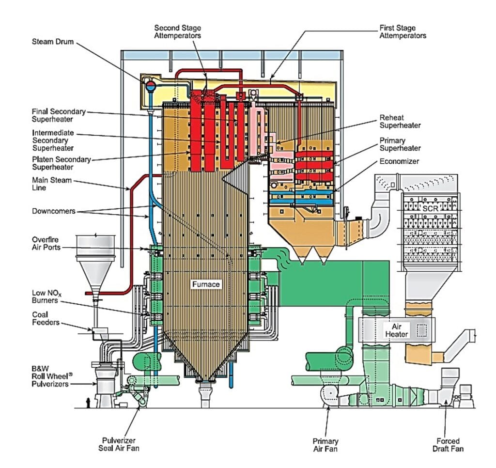
- Boiler Drum
- Dimensions: 15.7 meters in length, 1976 mm in inner diameter, and 132 mm in thickness.
- Material: Constructed from SA299 Grade A-1 carbon steel through fusion welding.
- Functions: The boiler drum acts as the central hub where water and steam circulate. It houses level indicators, safety valves, and a separating chamber, where steam undergoes initial purification through turbo separators and drying screens. The drum is maintained at a specific water level, leaving space for steam collection at the top.
- Downcomers
- Material: Made of SA106 Grade C.
- Structure: Six downcomers connect the boiler drum to the ring main header. These pipes supply water to the water wall tubes, supporting circulation and maintaining pressure consistency.
- Water Walls
- Material: SA 210 Grade A1.
- Design: Water wall tubes are formed into membrane panels, each comprising 22 tubes. The panels create a water-cooled barrier surrounding the furnace, aiding in heat absorption and steam generation. As water moves through the tubes, it heats up naturally, rising back to the boiler drum.
- Furnace
- Dimensions: Width – 13.868 m; Depth – 10.592 m; Volume – 5494 m³.
- Design: The furnace is a tall, rectangular structure, with a two-pass system. The first pass, or firing zone, is where fuel combustion occurs, reaching temperatures up to 1200-1400°C. The second pass contains the primary superheater, economizer, and air heater, promoting heat recovery and fuel efficiency.
- Superheaters
- Superheaters increase steam temperature above its boiling point, improving efficiency and thermal performance:
- Primary Superheater (LTSH): Operates between 450-480°C.
- Platen Superheater: Positioned vertically within the furnace, handling temperatures up to 580°C.
- Final Superheater: Located behind the reheater, further increases steam temperature to around 580°C.
- Superheaters increase steam temperature above its boiling point, improving efficiency and thermal performance:
- Reheater
- Purpose: After steam passes through the high-pressure turbine, it flows to the reheater for reheating before entering the intermediate-pressure turbine. This process boosts overall efficiency.
- Material: Made from SA213 T11 alloy steel, capable of withstanding temperatures up to 550°C.
- Economizer
- Location: Between the LTSH and air heater in the furnace’s second pass.
- Function: Preheats feedwater by capturing residual heat from flue gases, enhancing fuel efficiency. Preheated water then enters the boiler drum, reducing the energy required to reach steam generation temperatures.
- Windbox
- Design: The windbox is situated at an 11 m level and has 13 compartments to ensure effective air distribution to the furnace for fuel combustion. Secondary air is regulated to maintain combustion efficiency.
- Burners and Igniters
- Fuel: Coal serves as the primary fuel, with oil used during startup and low-load conditions.
- Arrangement: Burners are distributed across three levels (AB, CD, EF) with four burners each, controlled by high-energy arc igniters.
- Soot Blowers
- Soot blowers maintain boiler efficiency by clearing soot deposits from the boiler tubes. They are classified as:
- Wall Soot Blowers: Clean the furnace walls.
- Long Retractable Soot Blowers (LRSB): Located in the second pass, they clean the superheater and reheater.
- Air Heater Soot Blowers: Ensure the air heater remains free of soot for effective heat transfer.

Conclusion
- Modern boiler construction is a blend of engineering precision, material science, and safety considerations.
- Each component, from the boiler drum to the economizer, plays a pivotal role in maximizing efficiency and ensuring consistent steam production.


