Table of Contents
ToggleAn Ash Handling Plant is a critical component in thermal power stations where coal combustion produces ash as a byproduct. The plant handles both fly ash (light particles) and bottom ash (heavier particles) efficiently.
Ash handling in a thermal power plant refers to the method of collecting, conveying, storing, and disposing of various types of ash residue produced from solid fuel combustion. Proper ash handling is critical to the efficiency and environmental compliance of power plants.
Types of Ash
Bottom Ash and Slag
- Material that drops out of the furnace’s bottom in dry or wet (molten) form.
- Typically consists of large-sized clinker varying in size based on coal type and furnace temperature.
- Forms about 15-20% of the total ash.
- Collected in the bottom ash hopper beneath the combustion zone.
Economizer and Air Pre-Heater Ash
- Known as “grit,” or “Coarse ash” it consists of coarse particles (76 microns to 5 mm).
- Collected from flue gas streams in economizer and air pre-heater zones.
- Often combined with fly ash for removal.
Fly Ash
- Lighter ash particles carried away by flue gas.
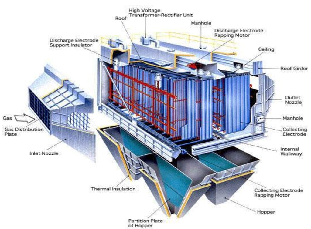
- Collected by Electrostatic Precipitators (ESPs).
- Particle size ranges between 10 to 76 microns.
Chemical Composition of Ash
The chemical makeup of ash varies, but typically consists of:
- Silica (SiO2): 48.0%
- Alumina (Al2O3): 26.0%
- Iron Oxide (Fe2O3): 10.0%
- Calcium Oxide (CaO): 4.0%
- Magnesium Oxide (MgO): 2.0%
- Sulphate (SO3): 1.2%
- Alkalies: 4.5%
Ash Handling Systems
Components of Wet Fly Ash (F.A.) System
- Fly Ash Hoppers
- Jet Pumps (Feeder Ejectors)
- Slurry Discharge Pipelines
- Slurry Tank
- Slurry Pumps
- Disposal Pond Pipelines
Components of Dry Fly Ash (F.A.) System
- Ash Hopper
- Air Lock Vessel
- Compressed Air Supply
- Ash Silo
- Fluidizing Pads
- Rotary Feeder
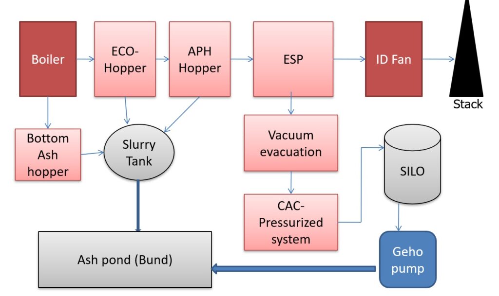
Process Flow of Ash Handling Plant

- Boiler:
- The boiler is the starting point of ash generation where coal combustion occurs, producing ash.
- Bottom Ash Hopper:
- Heavier ash particles settle at the bottom of the boiler and are collected in the Bottom Ash Hopper.
- Slurry Tank:
- The bottom ash is transported to the Slurry Tank, where it is mixed with water to form a slurry for further transportation.
- Ash Pond (Bund):
- The slurry from the tank is sent to the Ash Pond (bund) for safe disposal and storage.
- ECO-Hopper and APH Hopper:
- These hoppers collect ash from the flue gas generated during combustion.
- ECO Hopper collects ash from the economizer section.
- APH Hopper collects ash from the air preheater section.
- These hoppers collect ash from the flue gas generated during combustion.
- ESP (Electrostatic Precipitator):
- Fly ash in the flue gas is captured using the ESP to prevent it from being released into the atmosphere.
- ID Fan (Induced Draft Fan):
- The clean gas is drawn by the ID Fan and then discharged to the Stack for release into the environment.
- Vacuum Evacuation:
- Fly ash collected in ESP is transported using a Vacuum Evacuation System for further handling.
- CAC-Pressurized System:
- The ash is moved to the CAC-Pressurized System, where it is compacted and pressurized for easy transport.
- SILO:
- The collected ash is stored in a SILO, which acts as a temporary storage unit for dry ash.
- Geho Pump:
- The Geho Pump assists in transporting ash slurry to distant locations, such as ash ponds or disposal sites.
- Boiler:
General Description of Fly Ash Removal System
Fly ash is collected from flue gas passing through ESPs and stored in ESP hoppers. At the bottom of each hopper, feeder ejectors mix ash with high-pressure water (15 kg/cm²), creating a slurry. The slurry is then transported to a slurry tank and eventually disposed of in ash ponds by gravity.
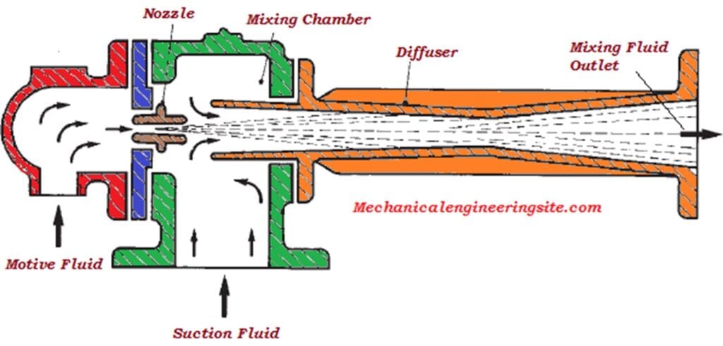
Construction of Feeder Ejector
- Body: Made of cast iron (C.I.), Y-shaped.
- Throat Piece and Venturi: Alloy C.I. with an adjustable nozzle for water flow control.
- Operation: High-pressure water creates velocity energy, which in turn generates a partial vacuum. This vacuum aids in drawing ash slurry from the tank for further disposal.
Operation of Feeder Ejector
- Ash falls by gravity into the feeder ejector body and is fluidized by incoming air.
- A vacuum created by high-pressure water ensures smooth flow without choking.
- The system prevents water from entering the ash body, ensuring dry ash flow.
Bottom Ash Handling System
- Bottom ash from the furnace is stored in a water-impounded hopper and discharged periodically.
- A 210 MW unit collects up to 50 tons of bottom ash every 8 hours, capable of being disposed of within one hour.
Key Features
- Hopper: Water-filled hopper chills and stores ash to minimize clinkering.
- Clinker Grinder: Reduces ash to 25 mm size for easier transport.
- Hydroejector: Uses pressurized water to create a slurry and transport ash to the disposal area.
Safety Mechanisms
- Pressure Switches: Detect blockages in ash transport lines, automatically halting grinder operations to prevent additional feeding.
- Reversing Mechanisms: Grinder reverses in case of overload to clear jams.
- Booster Water Pumps: Enhance water pressure for effective ash transport.

Fly Ash Handling for a 210 MW Unit
- Boilers burn coal at 1467 T/h, generating up to 57 T/h of fly ash.
- Removal is done hydraulically using devices like feeder ejectors designed by DEMECH in collaboration with Babcock Hyjropneumatics Ltd., UK.
Process Description
- Air Heater & Economizer Ash:
- Each hopper is equipped with isolator plates and slide valves for ash removal.
- Ash is mixed with water and flows to the slurry sump via gravity.
- ESP and Stack Fly Ash:
- Plate isolators and slide valves transfer ash to feeder ejectors.
- Ejectors mix ash with water to create slurry, which flows to the slurry sump.
Additional Details
- Intermediate Silo Storage: Fly ash collected from ESPs is sometimes stored in silos before further disposal. These silos are equipped with fluidizing pads to ensure the smooth flow of ash.
- Transport Systems: Pneumatic conveying systems are often used to transport dry fly ash to distant storage locations or for further utilization in construction materials like cement.
- Utilization: Fly ash can be used in the production of concrete, bricks, and road construction, reducing the environmental impact of ash disposal.
Hydraulic Transport Mechanism
- High-pressure water systems create slurries for both short and long-distance ash transport.
- The design of pipelines and slurry pumps ensures minimal wear and tear while maximizing transport efficiency.
Conclusion
Efficient ash handling is crucial for thermal power plants to ensure smooth operations and minimize environmental impact. By using both wet and dry systems tailored to specific types of ash, modern plants achieve effective collection, transportation, and disposal.
Recent posts
Related posts:
- Rankine Cycle in Thermal Power Plants
- Modes of Coal Transportation in Power Plant
- Coal Handling Plant – CHP
- Protections in Coal Handling Plants and Challenges
- Fuel Firing in Boiler
- Boiler Construction: History, Types, and Key Components
- Bowl Mill (Pulverizer) in Thermal Power Plant
- Coal Feeders in Power Plants
- Construction and Working of Air Preheater
- Electrostatic Precipitators (ESP)


Well I truly liked studying it. This article procured by you is very practical for proper planning.