Table of Contents
ToggleA zero crossing detector is a comparator, in which reference voltage is zero volt. It is also called as sine to square wave convertor. We have discussed Comparator using Op-Amp in our previous article.
A comparator is an electronic circuit, which compares the two inputs that are applied to it and produces an output. The output value of the comparator indicates which of the inputs is greater or lesser.
ZCD is also a comparator hence it does not have any feedback. Therefore, it is an open loop circuit. The open loop gain of op-amp is very high hence the output of a ZCD is always either positive saturation or negative saturation.
Zero crossing detector is divided into following two types.
- Non-inverting zero crossing detector
- Inverting zero crossing detector
Non-inverting Zero Crossing Detector
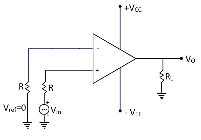
In Non-inverting Zero Crossing Detector (Non-inverting ZCD) the input is given to the non-inverting terminal and inverting terminal is grounded.
Circuit Diagram
The circuit diagram for a non-inverting ZCD is shown in the following figure.

Circuit operation
When the input goes on increasing from zero to positive the differential voltage is positive and hence op-amp will be in positive saturation i.e. +Vsat
When the input goes on decreasing from zero to negative the differential voltage is negative and hence op-amp will be in negative saturation i.e. -Vsat.
Thus, output voltage changes from one saturation level to another when the input makes a transition near to zero.
Input-Output Waveform
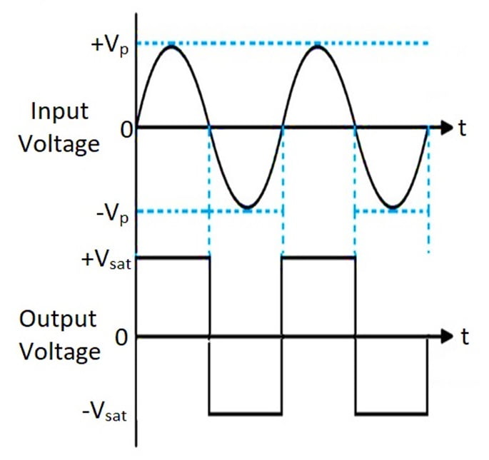
The input-output waveform for a non-inverting zero crossing detector is as shown below.

The output voltage is +Vsat for Vin > 0 and – Vsat for Vin < 0. Thus, in a non-inverting zero crossing detector the input is not inverted at output.
Inverting Zero Crossing Detector
In an inverting Zero Crossing Detector (Inverting ZCD) the input is given to the inverting terminal and non-inverting terminal is grounded.
Circuit Diagram
The circuit diagram for an inverting ZCD is shown in the following figure.

Circuit operation
When the input goes on increasing from zero to positive the differential voltage is negative and hence op-amp will be in negative saturation i.e. -Vsat.
When the input goes on decreasing from zero to negative the differential voltage is positive and hence op-amp will be in positive saturation i.e. +Vsat.
Thus, output voltage changes from one saturation level to another when the input makes a transition near to zero.
Input-Output Waveform
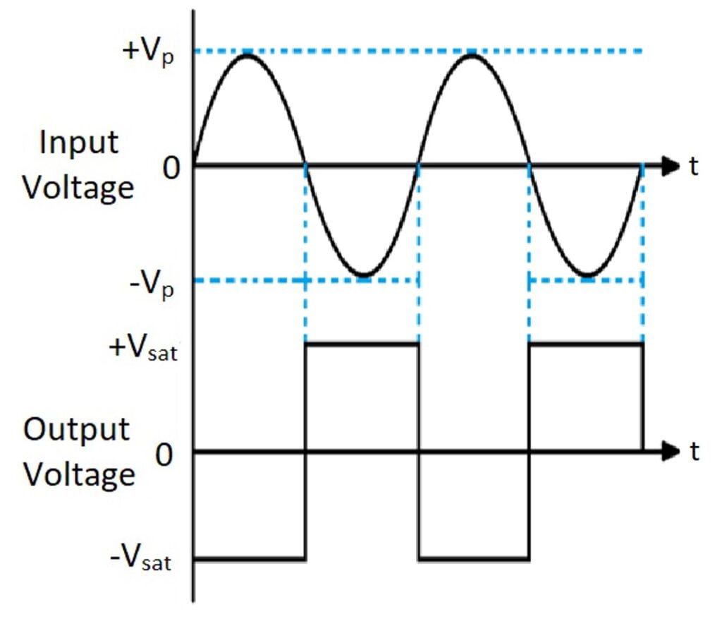
The input-output waveform for an inverting zero crossing detector is as shown below.

The output voltage is – Vsat for Vin > 0 and + Vsat for Vin < 0. Thus, in an inverting zero crossing detector the input is inverted at output.
Note: The input and output waveform of inverting ZCD and Non-inverting ZCD is exactly same as inverting and non-inverting open loop configuration of op-amp. In fact, these are nothing but the same circuits.
Disadvantage of Zero Crossing Detector
The noise present on the input side can cause false switching.
Applications of Zero Crossing Detector
- It is used as square wave generator.
- It is used in microprocessor based triggering circuit for thyristors.
Comparison between Comparator and Schmitt Trigger
Sr. No. | Comparator | Schmitt Trigger |
1. | It is an open loop system as it does not have feedback. | It is a closed loop system as it has positive feedback. |
2. | It has only one reference voltage. | It has two reference voltage. |
3. | It does not exhibit hysteresis. | It exhibits hysteresis. |
4. | It is used as voltage level detector | It is used to remove the noise between two reference voltages due to hysteresis. |
Video Tutorial on Zero Crossing Detector
Video Tutorial on Zero Crossing Detector in Hindi
Recent posts
Related posts:
- Introduction to Op-amp
- Parameters of Op-amp
- Configuration of Op-Amp
- Open Loop Configuration of Op-Amp
- Closed Loop Configuration of Op-Amp
- Virtual Short and Virtual Ground Concept
- Summing Amplifier Using Op-Amp | Adder Using Op-Amp
- Difference Amplifier Using Op-Amp | Subtractor Using Op-Amp
- Integrator Using Op-Amp
- Differentiator Using Op-Amp
- Comparator Using Op-Amp


Everything is very open with a clear clarification of the challenges. It was truly informative. Your site is extremely helpful. Thanks for sharing!