Table of Contents
ToggleAim
To calculate and verify Z-parameters of two-port network.
Apparatus
Breadboard, Batteries or DC regulated power supply, Resistors, Digital multimeter, Connecting wires, Alligator clips.
Theory
Z parameters (also known as impedance parameters or open-circuit parameters) are properties used in electrical engineering to describe the electrical behaviour of linear networks.
These Z-parameters are used in Z-matrixes (impedance matrixes) to calculate the incoming and outgoing voltages and currents of a network.
Z parameter is a factor by which input voltage and current and output voltage and current of two port network is related with.
For any two-port network, input voltage V1 and output voltage V2 can be expressed in terms of input current I1 and output current I2 respectively.
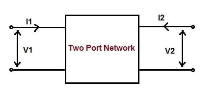
Z parameter in terms of input voltage V1 and output voltage V2 and input current I1 and output current I2 is given as below.
[ V ] = [ Z ] [ I ]
Where [Z] is impedance matrix, [V] and [I] are voltage and current matrix. Therefore, in matrix form the input and output voltage and current can be represented as below.
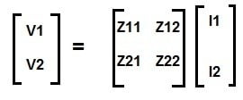
Form the above matrix, we get,
V1 = Z11I1 + Z12I2 …(1)
V2 = Z21I1 + Z22I2 … (2)
The Z-parameters can be calculated by considering supply voltage at one port and the other port is open circuited.
There are four Z parameter for a two-port or four-terminal network. Their values are tabulated below.
Z11 | (V1 / I1) | Condition: Output port of the two-port network is open i.e. I2 = 0 |
Z21 | (V2 / I1) | |
Z12 | (V1 / I2) | Condition: Input port of the two-port network is open i.e. I1 = 0 |
Z22 | (V2 / I2) |
How to calculate Z-Parameters
Consider the following figure.
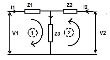
We know that,
V1 = Z11I1 + Z12I2 …(1)
V2 = Z21I1 + Z22I2 … (2)
Case1: Assume output port open i.e. I2 =0, voltage across impedance Z3 will be equal to V2.
V2 = Z3I1
Z3 = V2 / I1
But V2 / I1 = Z21,
∴Z21 = Z3 …(3)
Also, under the condition of output port open, applying Kirchhoff’s Loop Law in loop 1,
V1 = I1Z1 + V2
Diving both side of above expression by I1, we get
(V1 / I1) = Z1 + (V2 / I1)
But (V1 / I1) = Z11 and (V2 / I1) = Z21,
∴Z11 = Z1 + Z21
= Z1 + Z3 [from (3)]
∴Z11 = (Z1 + Z3)
Case2: Assume input port open i.e. I1 =0, voltage across impedance Z3 will be equal to V1.
V1 = Z3I2
Z3 = V1 / I2
But V1 / I2 = Z12,
∴Z12 = Z3 …(4)
Also applying Kirchhoff’s Loop Law in loop 2,
V2 = I2Z2 + V1
Diving both side of above expression by I2, we get
(V2 / I2) = Z2 + (V1 / I2)
But (V2 / I2) = Z22 and (V1 / I2) = Z12,
∴ Z22 = Z2 + Z12
= Z2 + Z3 [from (4)]
∴ Z22 = (Z2 + Z3)
Hence,
Z11 = (Z1 + Z3),
Z22 = (Z2 + Z3),
Z12 = Z3,
Z21 = Z3.
Significance of Different Z-Parameters
- Since Z11is the ratio of input voltage and current when the output port is open, therefore it is known as input driving point impedance. This can be understood as a transformer at no load. The input voltage is primary supply voltage Vs and the input current is excitation current Ie. Therefore, the input driving point impedance Z11 for this will be (Vs / Ie).
- Z22is the ratio of output voltage and current when input port is open, therefore it is called output driving point impedance of the network.
- Z12is the ratio of input voltage and output current when input port is open, therefore it is called reverse transfer impedance.
- Z21is the ratio of output voltage and input current when output port is open, therefore it is called forward transfer impedance.
Circuit Diagram

[Recommended values: R1= 2KΩ, R2= 450Ω, R3= 1kΩ, V1= 10V and V2= 5V OR chose any resistor between 200Ω to 2KΩ and DC supply beween 5V to 12V]
Procedure
- Connect the circuit as shown in figure 3.
- First open the output port and supply 10V to input port. Measure output voltage and input current.
- Secondly, open input port and supply 5V to output port. Measure input voltage and output current using multi-meter.
- Calculate the values of Z parameters using respective formulas (Shown in calculation section).
- Switch ‘OFF’ the supply after taking the readings.
Precautions
- Before circuit connection working condition of all the components must be checked.
- All the connection should be tight.
- Ammeter must be connected in series while voltmeter must be connected in parallel to the components (resistors).
- The electrical current should not flow the circuit for long time, otherwise its temperature will increase and the result will be affected.
Observation table
When output port is open circuited | When input port is open circuited | ||||
V1 | V2 | I1 | V1 | V2 | I2 |
|
|
|
|
|
|
Calculations
For Practical Values:
(a) When output is open circuited i.e. I2 = 0
Z11 = V1/I1 = ____Ω
Z21 =V2 /I1 = ____Ω
(b) When input is open circuited i.e. I1 = 0
Z12 = V1/I2 = ____Ω
Z22 = V2 /I2 = ____Ω.
For Theoretical Values:
Z11 = (R1 + R3)= ____Ω
Z22 = (R2 + R3)= ____Ω
Z12 = R3= ____Ω
Z21 = R3=____Ω
Result
Parameter→ | Z11 | Z12 | Z21 | Z22 |
Theoretical |
|
|
|
|
Practical |
|
|
|
|
Conclusion
Calculated and practical values of Z-parameters are found to be nearly equal hence ‘Z’ parameters are verified.
Video Tutorial on Z-Parameters
Video tutorial "To Verify Z-parameters of two-port network"
Recent posts
Related posts:
- Verification of Nortons Theorem
- Verification of Kirchhoffs Laws
- Verification of Superposition Theorem
- Verification of Thevenins theorem
- Verification of Maximum Power Transfer Theorem
- Verify Y-Parameters of Two-port Network
- Verify Hybrid Parameters of Two-port Network
- Study the transient response of a series RC circuit
- Study the transient response of a series RL circuit

