Table of Contents
ToggleAim
Verification of Maximum Power Transfer Theorem
Apparatus
Breadboard, Batteries or DC regulated power supply, Resistors, Digital multimeter, Connecting wires, Alligator clips, Computer and Multisim software for simulation.
Theory
Statement
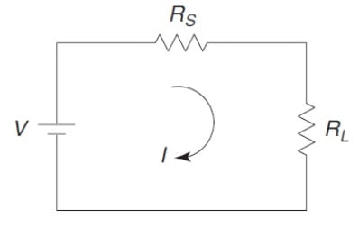
The maximum power transfer theorem states that in a linear, bilateral DC network, maximum power is delivered to the load when the load resistance is equal to the internal resistance of a source.

RS = Source resistance also called Thevenin’s resistance
RL = Load resistance
V = Source applied
I = Current flowing through the circuit
Steps to calculate Pmax by using Maximum power transfer theorem

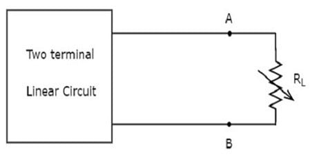
- Remove the variable load resistor RL.
- Find the open circuit voltage VTH across points A and
- Find the resistance RTH as seen from points A and
- Find the resistance RLfor maximum power
- Find the current
- Find the maximum power by using formula
OR
Applications of maximum power transfer theorem
- In radio communication, there is often a requirement to match the source impedance (at the transmitter) to the load impedance (such as an antenna) to avoid reflections in the transmission line that could overload or damage the transmitter.
- It is also applied in audio systems, where the voice is to be transmitted to the speaker. The amplifier amplifies the maximum amount of voice when the load impedance is equal to the source impedance.
- In car or any automobiles, if the effective resistance of the motor and the internal resistance of the battery are equal then maximum power will be transferred from battery to the motor to turn ON the engine.
Circuit Diagram

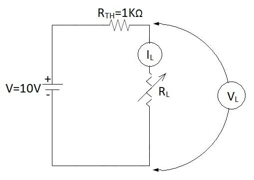
[You can take any value of source resistance RTH and then can vary load resistor with respect to RTH , accordingly make changes in observation table.]
Procedure
- Connect the circuit as shown in the figure 3.
- Vary the load resistor RL in steps of 100Ω and take the readings of voltmeter (VL) and ammeter (IL) for different values of RL.
- Take 10 to 15 readings as per observation table.
- Calculate power P for each value of RL.
- Plot the graph RL on X-axis versus power P on Y-axis.
Precautions
- Before circuit connection working condition of all the components must be checked.
- All the connection should be tight.
- Ammeter must be connected in series while voltmeter must be connected in parallel to the components (resistors).
- The electrical current should not flow the circuit for long time, otherwise its temperature will increase and the result will be affected.
Observation table
Sr. No. | RL (Ω) | VL (V) | IL (mA) | P= VL IL (mW) |
1. | 500Ω |
|
|
|
2. | 600Ω |
|
|
|
3. | 700Ω |
|
|
|
4. | 800Ω |
|
|
|
5. | 900Ω |
|
|
|
6. | 1000Ω |
|
|
|
7. | 1100Ω |
|
|
|
8. | 1200Ω |
|
|
|
9. | 1300Ω |
|
|
|
10. | 1400Ω |
|
|
|
11. | 1500Ω |
|
|
|
12. | 1600Ω |
|
|
|
Calculations
RS = RTH = 1KΩ
V = VTH = 10V
Theoretically maximum power delivered by the source to load resistance,
Result
Calculated maximum power delivered by the source to load resistance Pmax=
Practically maximum power delivered by the source to load resistance Pmax=
Conclusion
Power delivered by the source to load resistor is maximum when load resistance is equal to source resistance (RL = RS). Also Theoretical and practical value of maximum power is found to be nearly same hence maximum power transfer theorem is verified.


To the electronicsforyou.in webmaster, Thanks for the well-presented post!
Dear electronicsforyou.in admin, Your posts are always well-supported by facts and figures.
Hello electronicsforyou.in owner, Your posts are always well-supported by research and data.